OSHE Growbot Electrical
Description of System
The electrical system of the Growbot platform is controlled by a Raspberry Pi 4 and is separated into power distribution, drive train controls, and sensor controls. Power distribution consists of a single 6s LiPo 22.2V Battery that powers a nominal voltage rail with the O-Drive Motor Control Board attached and by extension, the Turnigy Outrunning Motors. Between the nominal rail and the O-Drive Motor Control Board is an Emergency Stop system that utilizes an automotive relay to cut power from reaching the control board. Additionally, the battery has a voltage sensor attached to it that will monitor the battery and be able to alert the raspberry pi (through the ADC) of the decreasing battery level throughout use. That 22.2V battery is then stepped down to 5V control power using a 5V regulator and is brought to a set of rails. These rails power the Raspberry Pi 4, the Analog to Digital Converter, and the rest of the sensors on the Growbot platform. Drive train controls consist of the Motor Control Board and Turnigy Outrunning Motor setup. These motors are controlled by the control board which receives its commands from the Raspberry Pi 4. Sensor controls consist of all of the sensors and the sensor-related electronics of the Growbot platform, with the exclusion of the voltage sensor.
Procedure - Main Electronics Board
| Description | Count |
|---|---|
| Raspberry Pi 4 | 1 |
| O-Drive Control Board | 1 |
| 50W Power Resistor | 1 |
| 6s LiPo 22.2V Battery | 1 |
| Voltage Sensor | 1 |
| 5V Regulator | 1 |
| Analog to Digital Converter | 1 |
| Large Power Rail (for 24V) | 1 |
| Small Power Rail (for 5V/GND) | 2 |
| Automotive Relay | 1 |
| Relay Holder | 1 |
| M2.5x10 Screws | 14 |
| M3 Nylon Standoffs | 4 |
| M4x10 Screws | 2 |
| M5x10 Screws | 2 |
| M2.5 Allen Wrench |
| M4 Allen Wrench |
| M5 Allen Wrench |
- Layout the following electrical components on the main electronics board keeping systems together (ie. power distribution, drive train, sensors). Make sure that there is enough room for all of these components and there is room for the necessary wiring.
- Battery mount
- Relay Mount
- Rails (x3)
- O-Drive Motor Control Board
- 50W Power Resistor
- Raspberry Pi 4
- 5V Regulator
- Voltage Sensor
- Secure the components listed above to the main electronics board using M3 Nylon Standoffs for the O-Drive Motor Control Board (x4), M5x10 screws for the 5V Regulator (x2), M4x10 screws for the largest rail (x2), and M2.5x10 screws for the rest of the components (x14).
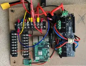
- Place the battery and relay into their appropriate mounts.
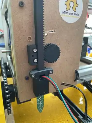
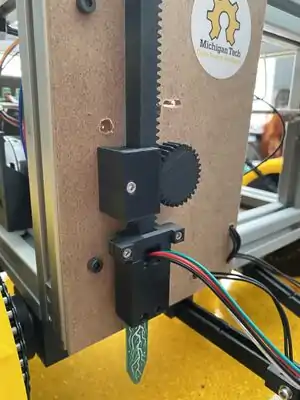
Procedure - Soil Sensor Mechanism
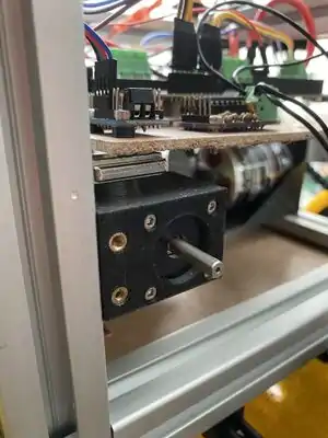
This probing mechanism uses a NEMA11 stepper motor to drive a rack with the sensor on the end. This mechanism can easily be adapted for any sensor that needs to be probed.
| Description | Count |
|---|---|
| M3 Heat Insert | 3 |
| 3030 L-bracket | 1 |
| M6x15mm | 1 |
| M4 3030 T-nut | 1 |
| M4x16mm | 1 |
| NEMA11 Motor | 1 |
| M2.5x6mm | 4 |
| M3 Hex Nut | 3 |
| M3x5mm Set Screw | 1 |
| M3x10mm | 2 |
| M2.5x10mm | 4 |
| M2.5 Hex Nut | 4 |
| Stemma Soil Sensor | 1 |
| M3x12mm | 2 |
| M3x16mm | 1 |
| Soldering Iron |
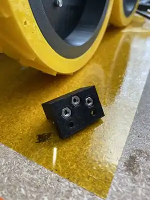
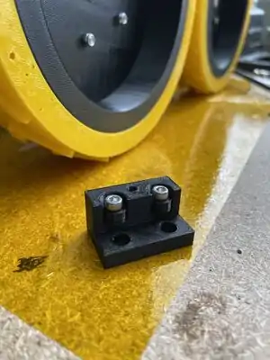
- StepperMount will need two M3 heat inserts installed. Using the 72mmMeasureBlock and 3030 L-bracket, attach the StepperMount to the 3030 rail. You will also need M4x16 and M4 Tnut to attach the StepperMount.
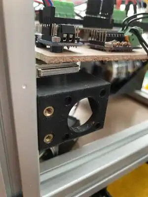
- Using four M2.5x6 bolts attach the NEMA11 motor to the MouterMount.
- Place external front panel onto bot.
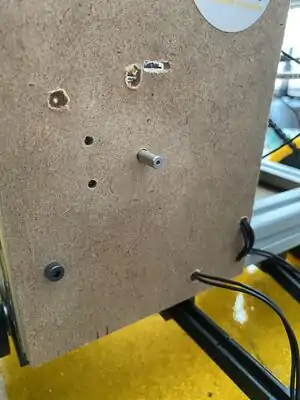
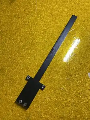
- Insert three M3 nuts into SensorRackTrack.
- Place Bearing into cylindrical cutout of SensorRackTrack. Attach with two M3x12 bolts.
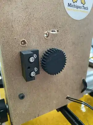
- Install M3 heat insert. Attach PinionGear with M3 setscrew. Attach SensorRackTrack with two M3x10 bolts.
- Insert four M2.5 nuts into SensorRack.
- Place Stemma Soil Sensor into SensorRack.
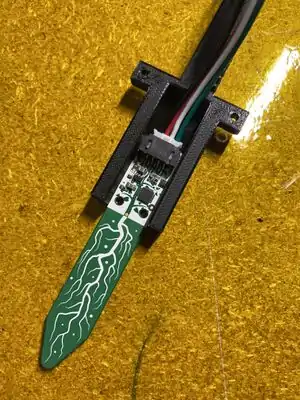
- Cover the sensor with the two piece cover, Top Cap and Bottom Cap, with four M2.5x10 bolts.
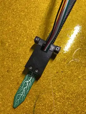
- Insert the SensorRackAssembly into the SensorRackTrack.
- Attach SensorRackCover with a M3x16 bolt.
Procedure - Ambient Sensors
| Description | Count |
|---|---|
| 9-Degrees-of-Freedom Sensor | 1 |
| Webcam | 1 |
| Temperature and Humidity Sensor | 1 |
| Growbot | ||
| Overview | ||
| Growbot Printed Parts Glossary | ||
| Growbot Bill of Materials | ||
| Growbot Tools Needed | ||
| Preparatory Materials | ||
| Metal Prep | ||
| Wire Harness Prep | ||
| Assembly | ||
| Frame | ||
| Motor | ||
| Axle | ||
| Drivetrain | ||
| Sensors | ||
| Guidance System | ||
| Electrical | ||
| Final Mechanical Assembly | ||
| Wiring | ||
| Firmware Installation | ||
| Follow-up information | ||
| Growbot SOP | ||
| Maintenance |