X
wikiHow is a “wiki,” similar to Wikipedia, which means that many of our articles are co-written by multiple authors. To create this article, 13 people, some anonymous, worked to edit and improve it over time.
This article has been viewed 3,410 times.
Learn more...
This article will give instructions in a simple way to create a bullet with casing in almost any 3D application. However this is only a modelling tutorial. We'll not be applying any material and rendering the bullet.
Steps
Part 1
Part 1 of 4:Set up your Work
Part 1
-
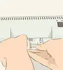
1Use a reference image. This is required for modelling. Go to the web and download an image showing the schematic of a bullet with its case.
-
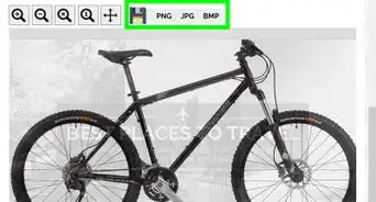
2Check the dimensions of your reference image. Right click on the reference image. Then, click properties and go to the details tab.
-
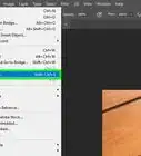
3Start 3DS Max.
-
4Change your view to Perspective for easy editing. Click on the bottom right window, then press Alt + W on keyboard to maximize your perspective view..
-
5
-
6
-
7Modify the length and width of your plane from the modify panel.
- Divide your reference image length and width pixel count by 10 (e.g.: 506 pixels will be 50.6mm) and change the length and width parameters of plane in mm. This will allow you to use the image without altering the aspect ratio of the picture.
-
8
-
9
-
10
-
11Align the plane to start modeling.
- Select rotate tool (keyboard shortcut R).
- Select angle snap to rotate in 5 degree increments for ease (keyboard shortcut A).
- Rotate 90 degrees on the z-axis.
- Rotate 90 degrees on y-axis.
- Select move tool (keyboard shortcut W), then move the plane back on its x-axis.


Part 2
Part 2 of 4:Start modelling the Bullet Case
Part 2
-
1
-
2
-
3
-
4
-
5
-
6
-
7Extrude the vertices to add more height.
- Click on vertex button from edit poly modifier.
- Click and drag to select all the top vertices of the cylinder.
- Click on the small button next to extrude.
- Extrude the vertices using setting box opened. Do twice since the bullet casing has two bends at the top.
-
8Create bullet case bottom notch.
- Select all the bottom vertices.
- Align the selected vertices to top part of the notch, on the z axis, as shown below with the reference image.
- Extrude again. Do it twice exactly to match the edges for the notch.
- Click on faces button in modifier panel.
- Then select the ring of faces (one up from bottom) as shown in the picture.
- Extrude the faces negatively. In this image below a value of -5mm is used.
- Select bottom most ring of faces.
- Scale them on xy axis by clicking on the select & uniform scale in toolbar (keyboard shortcut R).
- Hover mouse on xy plane of the pivot as shown in the figure. Then click and drag to scale.
-
9


Part 3
Part 3 of 4:Model the Bullet
Part 3
-
1Add a new cylinder for the bullet. This cylinder will be the actual bullet.
- Go to "Create" tab.
- Click on cylinder in standard primitives, then click and drag in the viewport.
-
2Adjust the dimensions of the second cylinder. Position it to the bullet in the reference image.
-
3Adjust the radius to be smaller than the first cylinder. Don't let it be too small to leave a visible gap in between the two cylinders.
-
4
-
5
-
6Create a round dome shape.
- Click on vertices select tool.
- Select all the newly created vertices along with the top vertices.
- Scale the ring of vertices to smaller size on the xy axis.
- De-select the bottom most ring.
- Scale it down again on the xy axis.
- Repeat scaling two more times and de-select one ring of vertices from bottom every time you scale down to give it a crude, dome like shape.
-
7Model the bullet point.
- Click on face select tool.
- Select the top face of bullet.
- Delete the top face.
- Select all the top vertices.
- Do a negative extrude as much as possible with a very small gap.
- Click on the Weld tool in modifiers panel.
- Weld all these extruded top vertices.
- Select and pull the new welded vertice to the top using the move tool.
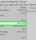
- Click modifier list from the modifier panel.
- Select and add "Turbosmooth" from the drop down menu. This will give the bullet a smooth look.


Part 4
Part 4 of 4:Add Finishing Touches
Part 4


Things You'll Need
- Reference image of a bullet showing schematic.
- 3DS Max or similar 3D software installed in your system.