X
wikiHow is a “wiki,” similar to Wikipedia, which means that many of our articles are co-written by multiple authors. To create this article, volunteer authors worked to edit and improve it over time.
Learn more...
This article is meant to help those with a basic understanding of Siemens NX 12.0 to be able to create a simple bluetooth chip (non-functional). This involves having a good understanding of the Datum Plane that exists in the NX 12.0 workspace, as well as a good understanding of the functionality of NX 12.0. This is not meant for people that are brand new to NX 12.0, however with enough practice this small project is definitely achievable to a novice NX 12.0 user.
Steps
-
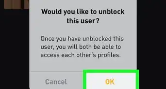
1Open up program NX 12.0 and click on "New". You will be directed to the New Part window[1]
-
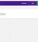
2While in the New Part Window, make sure model is selected, and make sure the dimensions are in mm. Then, name the file name an appropriate name, such as "Simple_Chip.prt". After this is completed click on "OK" in the bottom right, the program will take a few moments to load your new .prt file. When it is completed you will see an empty workspace
-
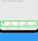
3Click on the "Sketch" creation tool in the top left to create a new sketch.
-
4A "Create Sketch" Window will appear, make sure the settings for the new sketch are as shown above, with the sketch being present in the x-y plane. After this is done click on "OK"
-
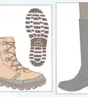
5Press the "r" key on your keyboard. This will bring up the rectangle tool, and you will have to specify a starting point. In this case, this is at the origin point. For the width, put in 4.3mm, and the height is 4.3mm as well.[2]
-
6Click your mouse anywhere on the workspace once. Then press the "Escape" key and the above sketch will have been created.
-
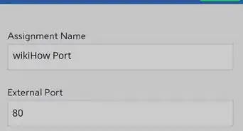
7Press the "x" key on your keyboard. This will bring up the extrude tool, which is used for making 2-Dimensional sketches into 3-Dimensional objects. Make sure all the values match those that are above. The only change that will have to be made is changing the "End" value to 1mm, after this click on "Apply"
-
8Click on the "Sketch" button in the top left to create a new Sketch.Then select the top face of the object(the one facing in the positive z direction). This is to create a space to draw the circuitry on top of the created object. Click "OK" and the point of view of the workspace will change, with the perspective being looking over the top of the object
-
9Press the "r" key on your keyboard to begin creating the antennae. This will bring up the rectangle tool, however this time coordinates will have to be put in so that the antennae is in the correct location in relation to the rest of the chip. Put in the coordinates (-1.5, 3.5), then put in the dimensions 1.2 for the width, and 3.5 for the height. It should then look like the rectangle above.[3]
-
10Press the "r" key again on your keyboard to begin creating smaller rectangles(resistors and capacitors) on the circuit. This will bring up the rectangle tool, and starting at coordinates (-4,4), begin creating rectangles that have height 0.3 mm and width 0.3 mm and are spaced out by 0.2 mm. This will take some time so make sure that all coordinates are correct. The finished sketch should look like the figure above.
-
11Press the "x" key on your keyboard. This will bring up the extrude tool, and will be used on the entire sketch that was just created on top of the rectangular face. This includes the resistors/conductors and the antennae. The only value that will have to be changed after selecting all the components is the end distance value, which will be 0.3 mm. The workspace will show a preview of the extruded object, so do not be alarmed if the workspace changes points of view dramatically. Click on "Apply" after this is completed
-
12Press the "L" key on your keyboard. This will bring up the line tool, and this will be used to connect the smaller rectangles to the antennae. This only needs to be done to 1 or 2 small rectangles, as the power that flows will be shared between the smaller rectangles and the antennae. An example configuration is shown above, however the connections can be done in any way since this is a non-functioning 3-D object.
-
13Press the "x" key on your keyboard. This will bring up the extrude tool, which will be used to extrude the lines that were just created by a distance of 0.15 mm. The only value that has to be changed in the extrude window is the end distance, which should be set to 0.15 mm.
-
14Congratulations! You now have a simplified, finished, non-functioning 3-D model of a 4.0 Low Energy Bluetooth Chip!