Delta Extruder Drive Assembly:MOST
 |
Michigan Tech's Open Sustainability Technology Lab.
Wanted: Students to make a distributed future with solar-powered open-source 3-D printing and recycling. |
 |
| This page is part of an international project to use RepRap 3-D printing to make OSAT for sustainable development. Learn more.
Research: Open source 3-D printing of OSAT • RecycleBot • LCA of home recycling • Green Distributed Recycling • Ethical Filament • LCA of distributed manufacturing • RepRap LCA Energy and CO2 • Solar-powered RepRaps • solar powered recyclebot • Feasibility hub • Mechanical testing • RepRap printing protocol: MOST• Lessons learned • MOST RepRap Build • MOST Prusa Build • MOST HS RepRap build • RepRap Print Server Make me: Want to build a MOST RepRap? - Start here! • Delta Build Overview:MOST • Athena Build Overview • MOST metal 3-D printer • Humanitarian Crisis Response 3-D Printer |
Materials and Tools
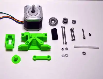 Extruder drive materials.
|
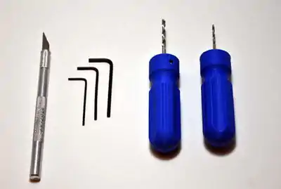 Necessary tools for Extruder drive.
|
Note
An extruder consists of two ends - a hot end and a cold end. This portion of assembly covers construction of the cold end, or extruder drive, the part of the system that pushes the filament into the hot end. The extruder drive is a pinch-wheel design wherein filament is pinched between a preloaded idler bearing and a toothed drive gear. Filament is pushed hard against the drive gear by the preloaded idler so that the teeth in the drive gear engage the filament, forming something akin a rack-and-pinion drive. The stepper motor then pushes the filament into a Bowden cable, where the filament is constrained and can only exit through the nozzle in the hot end.
A modified Airtripper's extruder drive is used on the MOST Delta, you are encouraged to visit the developers page to learn more about it. Modifications consist of moving the filament path away from the drive gear and adding an infeed tube to facilitate live-changing. Other slight non-performance modifications were also made.
Procedure
Video instructions
| Extruder Drive Assembly |
|---|
Step-by-step instructions
- Ream the 3mm holes in the drive body and linking rod with a 3mm drill bit.
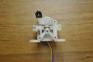
- Place the Mk7 drive gear on the motor with the set screw on the flat side of the shaft. Place the MR105z bearing on the shaft above the drive gear.
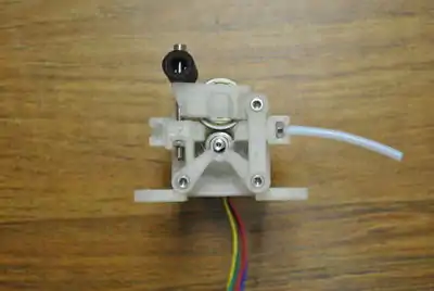
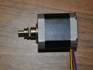 Motor with drive gear and bearing.
 - With the motor laying on the table, wires exiting towards you, orient the printed drive body with the conical section towards you, as shown in the picture. Make sure the vertical grooves of the Mk7 drive gear align with the plastic feed tube channel on the printed drive body.
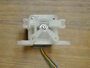 Motor with drive body properly oriented.
 - Start the M3 x 6mm button head screw in the top-left hole.
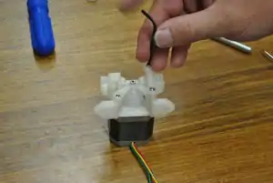 Drive body and linking rod attached to motor.
 - Start the M3 x 25mm screw in the bottom-left hole.
- Place the linking rod over the remaining mounting holes on the right side such that the screw head recesses face up. Start a pair of M3 x 30mm screws into the mounting holes.
- Tighten all of the screws except for the floating end of the linking rod, firmly affixing the drive body to the motor.
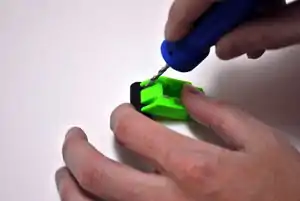
- With the 2mm drill bit, ream the filament path in the printed drive body as shown in the picture.
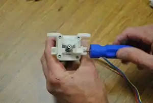 Ream the filament path.
 - Push a short piece of 1.75mm filament or a 1.5mm hex key through the filament path and align the knurled groove in the drive gear with the filament or hex key. When the drive gear is positioned properly, hold it in place and tighten the drive gear set screw with a 1.5mm hex key.
 Ream the filament path.
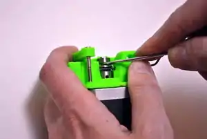
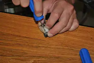
 - Cut off the circular base from the printed idler bearing shaft and smooth and round that end of the shaft.
 Remove the base from the printed idler bearing shaft.
 - Push the shaft through the 608zz bearing and snap the shaft and bearing into the idler cap.
 Assembled idler.
 - The drive uses the small piece of rubber fuel line as a compression spring. Two holes must be drilled to align with the slots in the end of the printed idler housing. Lay the housing on the hose and mark the first hole with the 3mm drill bit. Drill through the fuel line at the mark.
 Lay idler housing on fuel line to mark first hole.
 - Place washers on the two M3 x 45mm screws. Push one of the screws through the hole in the fuel line.
- Place the idler housing back on the fuel line with the screw in a slot as shown in the picture and mark the location of the second hole with the 3mm drill bit.
 Using one screw to align idler housing.
 - Drill the second hole in the fuel line and push the remaining M3 x 45mm screw with washer through the hole in the same direction as the first screw.
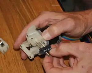 Attaching the fuel line to the drive.Getting the nuts started on the M3 x 45mm screws can be a challenge; laying the nut such that it rests against the screw boss as shown in the image can be helpful. Push the M3 x 45mm screws into their respective holes on the drive body and start a nut on each.
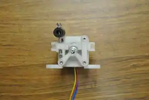 Hose-spring attached.
- Place the idler on its pivot (the screw under the floating end of the linking rod) and push the M3 x 45mm screws into the matching holes in the idler cap.
 Attaching idler.
 - Tighten M3 nuts on M3 x 45mm screws such that the hose is somewhat compressed.
 Idler in place.
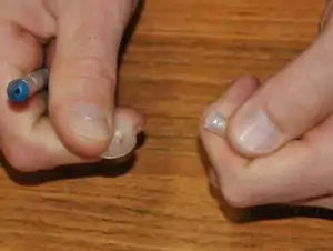
 - Cut a 30-40mm length 0f 2mm id x 4mm od PTFE tubing making sure that the cut is square and does not exceed 40 mm. Tube length in this step is not critical, and tubing should consequently be saved for the end effector. Slightly taper the end of the tubing with the precision knife or a pencil sharpener.
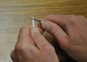 Cut and taper end of PTFE tubing.
 - Place the M4 nut on the 2mm drill bit and then push the drill bit into the tapered end of the short piece of PTFE tubing. Tightly grip the tubing and turn and push the nut onto it, forming threads. Continue threading until the tapered portion of the tube extends out of the nut. Cut the tapered portion off flush with the nut using the precision knife.
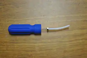 Plastiform threads in PTFE tubing.
 - Push the M4 nut into the pocket in the in-feed side (idler pivot side) of the printed drive body.
- Set the assembled extruder aside.
Navigation
| Tandem Build MOST Delta Navigation | |
| Green indicate workshop tasks | |
| Printer Primer | |
| Overview | |
| Soldering and tinning | |
| Assembling hot end | |
| Drilling Pilot Holes | |
| Person 1 | Person 2 |
|---|---|
| Tie Rods and Pulleys | Epoxying Magnets |
| Motor End Assembly | Idler End Assembly |
| Extruder Drive | Mount Bases |
| End Effector | Frame |
| Verticals | |
| Wiring | |
| Firmware | |
| Software | |
| Finishing | |
| Printing Basics | |