How to build Geared-Up From the Feet-Up
How to Build Your Own Geared-Up From the Feet-Up
Before you begin building, make sure you have these:
| Tools You Will Need |
|---|
| 1. Wrenches (socket, allen, crescent) |
| 2. Pliers |
| 3. Screwdrivers |
| 4. Power drill |
| 5. Table Saw |
| 6. Hacksaw |
| 7. Welding tools |
| 8. Blow torch |
| 9. Soldering Iron and tin |
| Materials you Will Need |
|---|
| 1. Bicycle Trainer Stand- We bought this from www.Amazon.com |
| 2. 36 Volt DC Permanent Magnet Motor- http://www.ebay.com/itm/ws/eBayISAPI.dll?ViewItem&item=370537871264& |
| 3. 40 Amp 600 Watt Blocking Diode- http://web.archive.org/web/20130306163648/http://www.windynation.com:80/products/accessories/conversion/diodes/40-amp-600-watt-stud-blocking-diode |
| 4. Single-Speed BMX Bike Chain-
Note: If there is a master link on the bike chain, remove it so it can fit through the derailleur and remove any excess links if necessary. |
| 5. Steel BMX Sprocket (28-tooth) |
| 6. Steel Sprocket (9-tooth) |
| 7. Derailleur |
| 8. Bike pedal crank lever still attached to sprocket from an old bike |
| 9. Fuse Holder |
| 10. 15 Amp Fuse |
| 11. 12 Volt DC Light bulb |
| 12. Light bulb socket |
Modifying the Bike stand
The Bike Stand:
- Set up your bike stand and remove the extra fan piece to expose the metal rod
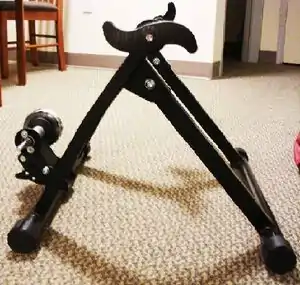 The Stand (Photo by Karen Stufkosky)
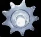
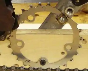
 - Get a sprocket. Any sprocket will do, but a larger gear will increase rotaions and make it easier on the rider.
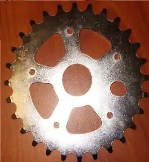 The gear!(Photo by Karen Stufkosky)
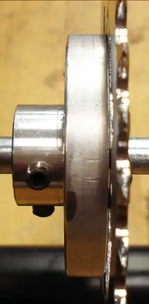
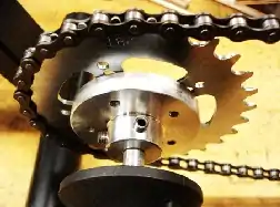
 - Slide the sprocket onto the rod of the bike stand and tighten screws, locking the piece into place.
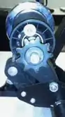 Roller with sprocket attached (Photo by Karen Stufkosky)
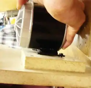
 - Etch the roller that contacts the rear bike tire to reduce the risk of slipping on the tire.
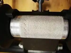 Etch the roller for grip (Photo by Karen Stufkosky)
 - The final bike stand roller should look like this.
 Roller after modifications and sprocket attached (Photo by Karen Stufkosky)
Applying the Derailleur
The Derailleur:
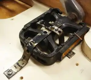
- Cut off the unnecessary sprocket attached to pedal leg, but keep gear intact because it will be used in step _.
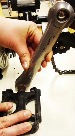 Remove sprocket from pedal leg (Photo by Karen Stufkosky)
 - Fit square bolt to the hole in the pedal leg.
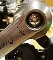 Fit square bolt to pedal leg (Photo by Karen Stufkosky)
This piece screws around the motor to hold tightly.
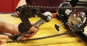
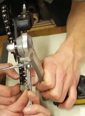
- Thread chain through derailleur. Derailleur should screw apart using a small wrench. Once derailleur is open, set chain in place and screw together again.
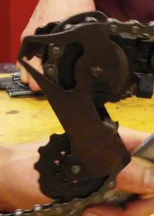 Attach chain to deraileur (Photo by Karen Stufkosky)
 - Using the bolt fitted to the pedal leg in step 2, now attach the derailleur to it with a washer and nut.
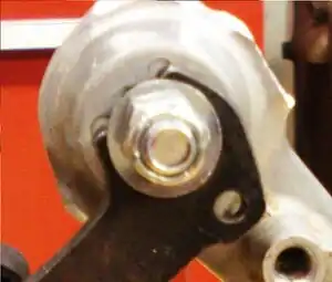 Bolt derailleur to pedal leg (Photo by Karen Stufkosky)
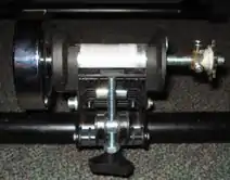
 - At this point your system should look like this.
 Derailleur attached to bike stand (Photo by Karen Stufkosky)
Modifying the Motor
Modify the Motor:
- Remove sprocket from the motor.
 Remove sprocket (Photo by Karen Stufkosky)
 - Cut a fitted hollow cylinder out of raw aluminum with screw holes to the sprocket.
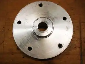 The gear mount(Photo by Karen Stufkosky)
 - Weld an aluminum cylinder to the disc that will fit the rod of the motor.
 Screw your gear and mount together(Photo by Karen Stufkosky)
This piece screws around the roller to hold tightly.
- Motor with gear attached (Photo by Karen Stufkosky)
Mounting the Components in Place
Note: Exact placement will vary depending on the length of your chain. Be sure to test the angle of your derailleur to make sure it doesn't interfere with your gear on the roller. Once positioned, test the angles of your derailleur to make sure it fully extends.
Mounting the System:
- Get a piece of wood that fits behind the bike stand without interfering with the roller.
 A piece of wood (Photo credit Karen Stufkosky)
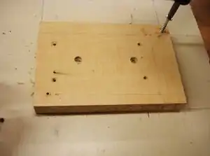
 - Optional: Cut a wedge out of the base of the board to allow for easier access to the height adjusting knob.
 Optional: cut out center (Photo credit Karen Stufkosky)
 - Screw a block of wood to the wood base, if you chose to cut out a piece in step 2, this piece of wood will do.
 Screw block of wood to the wood base (Photo credit Karen Stufkosky)
 - Screw motor to the piece of wood you attached in step 3, make sure the motor is aligned to the roller or you will loose power due to the excess resistance caused by the un-aligned chain.
 Motor screwed to block of wood (Photo credit Karen Stufkosky)
 - Now weave your chain onto the roller and motor sprockets.
 Chain attached to roller (Photo credit Karen Stufkosky)
 - Take the sprocket that you cut from the bike pedal, grind off a few teeth perpendicular to one of the 5 holes, and screw it into the bike pedal
 Sprocket used as stabilizer (Photo credit Karen Stufkosky)
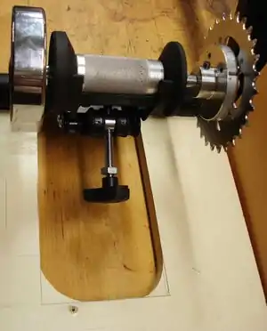
 - Test angle of derailleur mount to ensure the clearance of the roller when its adjusted.
 Test angle of derailleur (Photo credit Karen Stufkosky)
 - Decide on a spot to mount the pedal and screw it into place with metal brackets.
 Adjusting the pedal (Photo credit Karen Stufkosky)
 - Now that the pedal is mounted, slide a 1x2x5 inch piece of wood into the gab between the sprocket and the pedal. Screw it into place using at least 2 of the four remaining holes.
 Sprocket mounted (Photo by Karen Stufkosky)
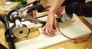
 - Your system should look like this.
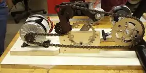 Everything mounted (Photo by Karen Stufkosky)
How to Wire the Electrical Circuit
Tools You Will Need:
- Soldering gun
- soldering tin
- wire strippers
- wire cutters
- screwdriver
Materials You Will Need:
- Blocking diode
- charge controller
- fuse (only one necessary)
- fuse holder
- insulated copper wire
- 25ft extension cord
- light bulb
- light bulb socket
- battery
Part 1: Wiring the Electric Circuit
Wiring the Electric Circuit:
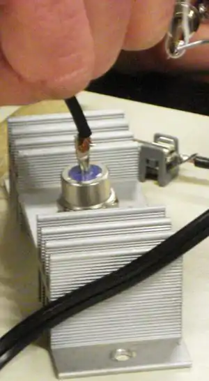
- Set blocking diode into heat sink positive (+) side-up by cutting hole to fit the diameter of the diode.
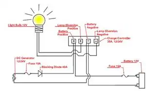 Electric Diagram (Photo credit Karen Stufkosky)
 - Solder positive (+) wire from the motor to the positive (+) side of blocking diode
 Blocking Diode (Photo credit Karen Stufkosky)
 - Solder (+) wire from blocking diode to one end of the fuse holder with fuse inside and solder another wire to the other end of the fuse holder.
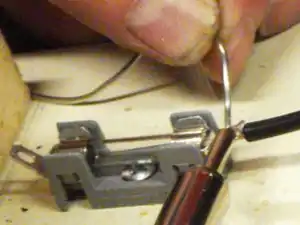 Fuse(Photo credit Karen Stufkosky)
 - What your circuit should look like
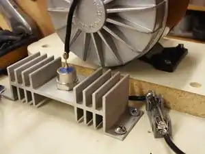 The circuit (Photo credit Karen Stufkosky)
 - Charge controller must be opened with screwdriver in order to connect wires
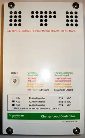 Chain attached to roller (Photo credit Karen Stufkosky)
 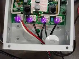 Charge Controler(Photo credit Karen Stufkosky)
6.1Place the positive (+) loose wire into the #1 “Battery Positive” terminal on the charge controller
6.2Place the Positive (+) wire that goes to the battery into the same #1 “Battery Positive” terminal on the charge controller.
6.3Screw both wires down, locking them into place. 6.4Take the negative (-) wire from the motor and place it into the #3 “Battery Negative” terminal of the charge controller.
6.5Take the negative (-) wire from the battery and place it into the same #3 “Battery Negative” terminal of the charge controller as well.
6.6Screw both motor and battery negative wires down, locking them into place together in the terminal
Part 2:Wiring the Diversion Load
Sorry, this part is still missing. Please add if you have information on how the diversion load was wired on this project.
Weatherproofing the System with a Plexiglass Case
How to build the Plexiglass Weatherproof Case:
- Cut plexi-glass pieces to fit around the wooden base.
 Plexi-glass (Photo credit Karen Stufkosky)
 - Glue plexi-glass pieces together with plexi-glass solvent to join the pieces, making a box.Plexi-glass (Photo credit Karen Stufkosky)
- The box must be opened periodically to maintain moving parts and tighten bolts. A hinged door makes this possible on the long side of the box next to the motor. Hinges are bolted to the top of the box and to a side piece of plexi-glass.
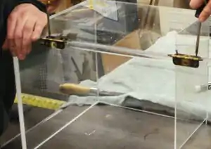 Attach Hinges(Photo credit Karen Stufkosky)
 - Affix magnet plates to bottom of door with screws. Screw magnets onto main wooden board.
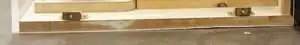 Attach magnets (Photo credit Karen Stufkosky)